
Items related to Radar for Mariners, Revised Edition (INTERNATIONAL...
Synopsis
Become an Expert Small-Craft Radar Operator
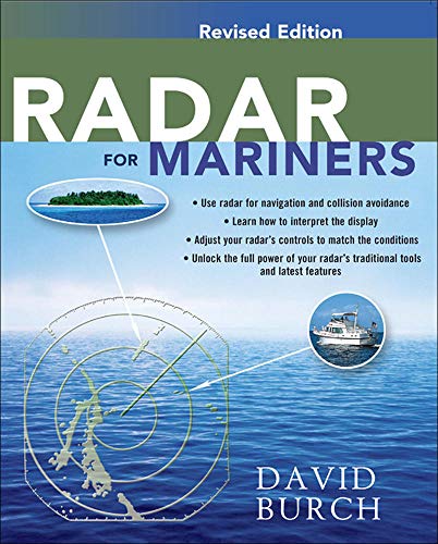
Nothing beats radar for guiding your boat through the darkest night or the thickest fog. Radar enables you to plot a fix from just a single buoy or landmark, and it is the only navigation tool that tells you not just where you are, but who else or what else is out there with you. Today's smaller, affordable, efficient radars make more sense than ever for sailors and powerboaters.
Adopted by the American Sailing Association for their radar course and used by professional and recreational radar training schools around the world, this complete, in-depth manual shows you how to:
- Choose the best radar model for your sailboat or powerboat
- Install, adjust, and operate your system
- Interpret the images on your radar screen
- Pilot your boat and track the movements of vessels around you
- Use radar to track and avoid squalls, outmaneuver competitors in a yacht race, and other specialized tasks
- Interface your radar with a digital compass, GPS, or electronic chart
"This book will turn you into an expert on small-craft radar operations. It covers everything--radar choice, installation, use, and how to interface with your electronics. Very comprehensive!" -- Boat Books
"Stands out among other books on the subject . . . an excellent introduction to radar." -- Power Cruising
"Radar is an electronic tool, the operation of which takes much more interpretation than any other--too little knowledge can be just as dangerous as none. Radar for Mariners helps you understand how radar works, explains its limitations, and shows you how to get the full use of radar's functions. This book should show up on the radar screen of anyone with radar--or contemplating getting one. I can't wait to go to my boat and stop playing with my radar and start using it." -- Good Old Boat
"synopsis" may belong to another edition of this title.
About the Author
David Burch, the director of the Starpath School of Navigation in Seattle, Washington, has been teaching navigation and seamanship since 1977. He has logged more than 60,000 sea miles, including three wins in the trans-Pacific Victoria to Maui yacht race. He is the author of nine books on marine navigation, including Emergency Navigation (International Marine, 1984), and his magazine articles have appeared in Cruising World, Ocean Navigator, Sailing, and Sea Kayaker. He holds a U.S. Coast Guard Master's license (100 tons). He is also a past Fulbright Scholar and holds a PhD in physics. HOMETOWN: Seattle, WA
Excerpt. © Reprinted by permission. All rights reserved.
RADAR FOR MARINERS
By DAVID F. BURCHMcGraw-Hill Education
Copyright © 2013 David F. Burch
All rights reserved.
ISBN: 978-0-07-183039-3All rights reserved.
Contents
| Preface | |
| Acknowledgments | |
| Part One WORKING KNOWLEDGE OF RADAR | |
| Chapter 1. HOW RADAR WORKS | |
| Chapter 2. OPERATION AND "TUNING" | |
| Chapter 3. INTERPRETING THE RADAR SCREEN | |
| Chapter 4. RADAR FOR POSITION NAVIGATION | |
| Chapter 5. RADAR PILOTING | |
| Chapter 6. RADAR FOR COLLISION AVOIDANCE | |
| Part Two BEYOND THE BASICS | |
| Chapter 7. INSTALLATION, SPECIFICATIONS, AND PERFORMANCE | |
| Chapter 8. SPECIAL CONTROLS AND FEATURES | |
| Chapter 9. FALSE ECHOES AND INTERFERENCE | |
| Chapter 10. ADVANCED NAVIGATION AND PILOTING | |
| Chapter 11. RADAR MANEUVERING | |
| Chapter 12. RADAR AND THE NAVIGATION RULES | |
| Chapter 13. LOOKING AHEAD | |
| APPENDIX | |
| Glossary | |
| List of Abbreviations | |
| References | |
| POSTSCRIPT: HIGH-DEFINITION (HD) AND BROADBAND RADAR | |
| INDEX |
CHAPTER 1
How Radar Works
Radar (radio detection and ranging) is an onboard electronic navigationinstrument that measures the range and bearing of landmasses and vessels in itsvicinity. It works by sending out a rotating beam of microwave pulses anddetecting the pulses that are reflected back from objects around it. It workslike a depth sounder, pointed toward the horizon rather than the bottom. As witha depth sounder, what we see on the radar screen are only electronic blips orechoes of the targets, not realistic representations. Also like a depth sounder—ora flashlight scanning a dark room—the radar beam only "sees" what is in viewof the beam at the moment. The radar's internal display electronics must paint apicture on the radar screen as the beam scans the horizon, refreshing it every 3seconds. It takes some practice to read a radar screen and interpret what isreally out there. We cover this in Chapter 3. As we shall see, some objects arebetter radar reflectors than others, which gives rise to the term radar target.A good radar target is one that sends back a strong, well-defined image to theradar screen. Figure 1-1 illustrates schematically how a radar operates.
Isolated targets such as other vessels, large buoys, islets, or drillingplatforms are easier to interpret than large, irregular landmasses. At longerdistances, isolated targets appear as simple dots or small line segments. Asthey get closer their target sizes increase, but unless an object is big andfairly close, the size of the echo on the radar screen (of a ship or buoy, forexample) is not a measure of the actual size of the target. This concept isexplained further in Chapter 3. The image or echo of a target seen on a radarscreen is sometimes called a blip.
The basic components of a radar system are an antenna, the radar display unit,and a power source—a typical radar consumes 30 to 40 watts when transmitting.The radar display unit includes a radar screen and a set of controls (knobs,buttons, and sometimes a track ball). There are sophisticated electronics inboth the display unit and the antenna, and it is generally most efficient tohave a professional electronics technician install and calibrate the systembefore use (installation options are discussed in Chapter 7). After properinstallation it runs dependably and requires little attention as a rule,although basic performance monitoring as discussed in Chapter 13 is alwaysprudent. Radar is a powerful broadcasting device, so an FCC (FederalCommunications Commission) Ship Station Radio License (or internationalequivalent outside the United States) may be required in some cases (see Chapter7). If you already have a license for a marine radio, the radar can be added toit without a new license.
What you see on the radar screen are your surroundings to a maximum distanceequal to the selected range setting. The word range is used many ways innavigation, but for radar, it simply means the distance from your vessel to theradar target. Typical small-craft radars have maximum ranges of 16 to 36 miles—shipradars extend out to 72 miles or more—but we have to cover more backgroundbefore we can appreciate the significance of these numbers. On the plan viewused on radar display screens, your vessel is in the center of the screen. Deadahead is usually straight up (at the top of the radar screen), your surroundingsto starboard are in the right half of the radar screen, your port side is on theleft, and aft at the bottom. Modern radars offer options to this display mode,but this head-up mode is the most fundamental and still the most common insmall-craft radar. Head-up display is illustrated in Figure 1-2, which shows aradar image overlaid on the chart region it is viewing. It is similar to theschematic view of Figure 1-1, but with real data.
Radar units are often loosely referred to by their maximum range. A "32-mileradar" has a maximum range of 32 miles but can also be set for 24 miles, 16miles, 8 miles, and so on. In the past (as well as in many units today), theavailable range options were fixed values. In some modern units, the user canchoose any range desired up to the maximum range of the unit. Also in the past,radar screens were circular, so if you selected a display range of 6 miles, thecircumference of the display was 6 miles away in all directions. Most modernradars screens are rectangular, with the display shifted slightly toward thebottom to show an extra ring forward. Today, a range setting of 6 miles willmore likely mean that you can see 6 miles to the right, left, and aft, andapproximately 7 miles dead ahead, as can be seen in Figure 1-3. In all modernunits, however, there is always an Offset function that lets the userarbitrarily shift the center location for longer looks in any direction. This iscovered in Chapter 8.
RANGES, BEARINGS, AND BUOYS
To navigate from what we see on the radar, we need numerical values of theranges and bearings to the various targets shown on the radar screen. The veryconvenient, electronic way of measuring these values with radar is one of theprimary virtues of the instrument.
Suppose we are looking for a buoy about 2 miles ahead on the starboard bowaccording to the chart and our GPS position. The first step in locating thisbuoy on the radar screen is to select the appropriate range scale. If the rangescale were set to only 1 mile, we would not see the target because it is morethan 1 mile away. When we increase the Range (by just pushing a button orturning a knob) to the 3-mile scale, however, we should see a target abouttwothirds of the way out from the center in the top right quadrant of thescreen. If we increase the Range again, to 6 miles, the target should remain atthe same relative bearing on the screen, but will now be nearer the center, justone-third of the way out, and will register as a smaller blip. If our rangeoptions were just 3 or 6 miles, the 3-mile scale would be the better choice.Generally the smallest range that shows the target of interest will give thebest results for range and bearing measurements. This lowest range, however,might not offer the best overall perspective for orientation, so one of thebasic things we learn in all aspects of radar usage is frequent switching ofranges to keep an eye on things up close and at a distance.
A large buoy, or one with a specially designed radar reflector on it, would showup much like a small vessel—just a little blip on the screen. The radar cannotgenerally tell you which of these you might be seeing—buoy or vessel—but if youwere expecting a buoy, that would be your first guess of what the target is. Asmall buoy might not show up at all at 2 miles off because it does not haveenough reflecting surface to send back a detectable signal, but larger ones willshow up nicely. We cover this subject more in Chapter 3.
The first estimate of a numerical value for the actual range to the buoy comesfrom the range rings. Each range scale on the radar comes with a set ofpredefined concentric rings at specific ranges. On the 3-mile or 6-mile ranges,these rings are typically drawn 1.0 mile apart. At 12 miles they might be at 2.0miles apart, and so on. Modern units often let the user select both the sequenceof ranges as well as the ring spacing within them, so you might see a 6-milerange with either 1- or 2-mile ring spacing. A typical radar shows the activeRange and Range Ring settings prominently in one corner of the display, such asR 3.0, RR 1.0. If we notice that a target is just inside the first range ring,then we know it is just less than 1 mile off. But we can do much better thanthat.
Every modern radar has a function called variable range marker (VRM). It is arange ring for which you can control the radius. The VRM is operated differentlyon different units, but all do the same thing. Press a button to turn it on, andthen press another button to vary the range of the ring. We cover the finerpoints of using the VRM in Chapter 4; for now, just set the VRM ring to coincidewith the closest edge of the buoy target, and then read the value numericallyfrom the VRM readout—in this case it might read 1.89 nm. You can measure veryaccurate distances this way if you have good radar targets—a term that willbecome more clear as we proceed.
If you are moving toward the buoy, you can watch it move down the screen,getting closer to you. Its motion is easy to detect, because it will move offthe VRM that you had set on its previous position. Readjust the VRM to see howmuch closer it is now. The value of the VRM cannot be overstated. It is not justfor watching isolated buoys or vessels moving on the screen, but also for moregeneral radar navigation. More specific examples are given in Chapters 5 and 12.We will also very shortly cover other ways to measure the distance to a radartarget.
A bearing to the buoy is just as easy to obtain. Here the tool is called theelectronic bearing line (EBL). Press a button to turn it on and a prominentradial line—along with its digital bearing—will appear in one corner of theradar display. Press another button (or turn a knob, depending on your model) torotate the line to the right or left. Adjust the EBL until the line goes throughthe center of the buoy target and read off its bearing, such as 048 or 048 R. Inhead-up display mode, these bearing measurements are usually in relative units,meaning relative to the bow of your boat, also called ship's heading or head. Inthis example, the buoy was located 48° to the right of the bow at the time ofmeasurement. Using relative units, dead ahead is 000, starboard beam is 090 R,aft is 180 R and port beam is 270 R. If the EBL had read 300 R, then the buoywould have been 60° to the left of the bow. Figure 1-4 illustrates relativebearings.
If we want a compass bearing to the buoy that we can use to look for the buoy ondeck, we need to correct the relative output of the EBL for our actual heading.Do this by adding the relative bearing to your course heading. If our compasscourse is 200 C at the time of the reading, for example, then the compassbearing to the buoy (located 48° to the right of the bow) is 248 C. When targetsare on the port side of the boat, with relative bearings greater than 180, it isbest to add the relative bearing to your heading and then subtract 360 asneeded. In the second example above, 200 (ship's heading) + 300 (relativebearing to buoy) = 500, and 500 - 360 = 140 degrees, which is the compassbearing to the buoy. For this and numerous other reasons, every nav stationshould have a simple calculator on hand at all times (large keys and a largedisplay are assets). It will prove useful often, as in compass conversions,speed-time-distance computations, and for some special quick computations neededfor radar, which we discuss later on.
(Later we discuss options in modern radars that let us read actual compassbearings or even true bearings directly from the radar without manuallycorrecting for vessel heading, but this requires an optional heading sensorinput to the radar.)
It is simple to get a bearing for any target we see on the radar using the EBL,but we must be mindful of several factors when we interpret the result. First,even though electronic bearings are typically specified to within a tenth of adegree, it is rare that the accuracy of the intended measurement has this levelof precision. In the head-up example given above, we had to correct for ourcourse heading of 200 degrees to get the buoy's compass bearing. But we may nothave been precisely on course at the time we noted the EBL reading. The ship'sheading will typically swing around a bit in a seaway, so the EBL will move onand off the target once it is set. In short, the accuracy of the bearing willdepend on the accuracy of your heading knowledge at the time of the measurement.With head-up display, careful coordination with the helmsman is needed forprecise bearing data; another solution is a digital heading output right on theradar screen so that you can record the EBL and heading at the same time. InChapter 7 we cover even more convenient interface options.
When taking bearings to tangents of large radar targets (as opposed to centersof small, well-defined targets like buoys), other considerations affect accuracyas well. We cover these in Chapter 10.
Another way to measure ranges and bearings with modern radar is to use a cursormode. In this mode a track ball or track pad is used to move a prominentcrosshair cursor around on the radar screen while at the same time displayingthe range and bearing to the cursor location somewhere on the radar screen. Wantthe range and bearing to a headland? Just roll the cursor over to that locationon the screen and read it off digitally in a bottom corner of the screen. Thisis a very convenient option, which sometimes includes a further option to drawan EBL and VRM circle through the cursor location by pressing buttons.
The cursor is generally the preferred method of finding target range andbearing. It has the advantage of being quick but the disadvantage of not leavingpermanent marks on the screen, as the VRM and EBL do. Underway you will havecall for both types of measurements, which opens the opportunity for errors. Apotentially serious error would be to set the cursor on a headland and then readthe output from the VRM, which is inadvertently set on some other location.Often the outputs on the screen are very similar and just marked by differenticons. It is often true with modern electronics that the more convenient ourtools, the more careful we have to be in using them. Sample measurements areshown in Figure 1-5.
Bearing and range measurements are fundamental to radar usage. To a radaroperator, VRM and EBL are acronyms as common as GPS or radar itself. We will useabbreviations throughout the rest of this book. VRM and EBL have several crucialapplications that cannot be replaced with the cursor mode feature, but when justa value of range or bearing is needed, the cursor mode will generally be thefirst choice for the job. In Chapter 2 we cover a related tool called theelectronic range and bearing line (ERBL). In Chapter 4 we cover ways to optimizethe accuracy of the measurements.
HEAD-UP DISPLAY MODE
Until recently, small-craft radar had only one display mode available—namely,the head-up mode using relative bearings for the EBL as discussed above. This isstill an option on all radar systems, and still the only option on many units inuse today. It is also in many ways the most fundamental mode and the easiest tointerpret. You think of your boat in the center of the screen, pointed straightup, and things you see around you on the radar screen are located relative toyour vessel. Look to the right of your boat for things on the right of thescreen; look back for things on the bottom of the screen, etc. The translationfrom radar image to the world around you is particularly direct and intuitive ifyour nav station faces forward. It is perhaps a bit less intuitive if your navstation faces athwart-ships or even aft, but in all cases this is a direct,easily interpreted radar display mode. Your heading line remains vertical, fromthe center to the top of the radar screen, regardless of your vessel heading orthe orientation of the display unit within your vessel. No special inputs to theradar are needed.
In head-up mode, when your course changes to the left, or counterclockwise, allradar targets rotate a corresponding amount to the right, or clockwise, but nomatter which way you head, the heading line remains straight up, and the top ofthe radar screen is the direction the bow is pointed. In head-up mode, the EBLreads out bearings to radar targets in relative units. Suppose the EBL is set ona target at 048 R (48° on the starboard bow), and then we turn away from it, 10°to the left. The heading line and the EBL will not move on the radar screen aswe turn, but the target will rotate right 10°, and is now 58° on the starboardbow. This illustrates the fundamental advantage of the head-up mode—things arewhere they appear to be on the radar—but it also illustrates an inherentdisadvantage when it comes to identifying what we see on the radar when we aremoving. If our heading is swinging about as we proceed along our course, as itwould in choppy water or a seaway, target positions will "smear" as they rotateback and forth in response to our heading swings. They get painted onto thescreen wherever they happen to be when the radar beam passes across them.
(Continues...)
Excerpted from RADAR FOR MARINERS by DAVID F. BURCH. Copyright © 2013 David F. Burch. Excerpted by permission of McGraw-Hill Education.
All rights reserved. No part of this excerpt may be reproduced or reprinted without permission in writing from the publisher.
Excerpts are provided by Dial-A-Book Inc. solely for the personal use of visitors to this web site.
"About this title" may belong to another edition of this title.
Search results for Radar for Mariners, Revised Edition (INTERNATIONAL...

Stock Image
Radar for Mariners, Revised Edition
Published by
McGraw-Hill Professional Publishing, 2013
ISBN 10: 0071830391
ISBN 13: 9780071830393
Used
Softcover
Seller: Better World Books Ltd, Dunfermline, United Kingdom
Seller rating 5 out of 5 stars

Condition: Good. Pages intact with minimal writing/highlighting. The binding may be loose and creased. Dust jackets/supplements are not included. Stock photo provided. Product includes identifying sticker. Better World Books: Buy Books. Do Good. Seller Inventory # 15416928-20
Buy Used
£ 17.06
£ 5 shipping
Ships from United Kingdom to U.S.A.
Ships from United Kingdom to U.S.A.
Quantity: 1 available
Seller Image
Radar for Mariners
Published by
International Marine/Ragged Mountain Press, 2013
ISBN 10: 0071830391
ISBN 13: 9780071830393
New
Softcover
Seller: GreatBookPrices, Columbia, MD, U.S.A.
Seller rating 5 out of 5 stars
Condition: New. Seller Inventory # 19510883-n
Seller Image
Radar for Mariners, Revised Edition (Paperback or Softback)
Published by
International Marine Publishing 6/11/2013, 2013
ISBN 10: 0071830391
ISBN 13: 9780071830393
New
Paperback or Softback
Seller: BargainBookStores, Grand Rapids, MI, U.S.A.
Seller rating 5 out of 5 stars
Paperback or Softback. Condition: New. Radar for Mariners, Revised Edition. Book. Seller Inventory # BBS-9780071830393
Seller Image
Radar for Mariners
Published by
International Marine/Ragged Mountain Press, 2013
ISBN 10: 0071830391
ISBN 13: 9780071830393
Used
Softcover
Seller: GreatBookPrices, Columbia, MD, U.S.A.
Seller rating 5 out of 5 stars
Condition: As New. Unread book in perfect condition. Seller Inventory # 19510883
Stock Image
Radar for Mariners, Revised Edition
Published by
International Marine/Ragged Mountain Press, 2013
ISBN 10: 0071830391
ISBN 13: 9780071830393
New
Softcover
Seller: California Books, Miami, FL, U.S.A.
Seller rating 4 out of 5 stars

Condition: New. Seller Inventory # I-9780071830393
Seller Image
Radar for Mariners, Revised Edition
Published by
McGraw-Hill Education - Europe, US, 2013
ISBN 10: 0071830391
ISBN 13: 9780071830393
New
Paperback
Seller: Rarewaves USA, HEBRON, KY, U.S.A.
Seller rating 5 out of 5 stars
Paperback. Condition: New. Become an Expert Small-Craft Radar OperatorNothing beats radar for guiding your boat through the darkest night or the thickest fog. Radar enables you to plot a fix from just a single buoy or landmark, and it is the only navigation tool that tells you not just where you are, but who else or what else is out there with you. Today's smaller, affordable, efficient radars make more sense than ever for sailors and powerboaters.Adopted by the American Sailing Association for their radar course and used by professional and recreational radar training schools around the world, this complete, in-depth manual shows you how to:Choose the best radar model for your sailboat or powerboatInstall, adjust, and operate your systemInterpret the images on your radar screenPilot your boat and track the movements of vessels around youUse radar to track and avoid squalls, outmaneuver competitors in a yacht race, and other specialized tasksInterface your radar with a digital compass, GPS, or electronic chart"This book will turn you into an expert on small-craft radar operations. It covers everything--radar choice, installation, use, and how to interface with your electronics. Very comprehensive!" -- Boat Books"Stands out among other books on the subject . . . an excellent introduction to radar." -- Power Cruising"Radar is an electronic tool, the operation of which takes much more interpretation than any other--too little knowledge can be just as dangerous as none. Radar for Mariners helps you understand how radar works, explains its limitations, and shows you how to get the full use of radar's functions. This book should show up on the radar screen of anyone with radar--or contemplating getting one. I can't wait to go to my boat and stop playing with my radar and start using it." -- Good Old Boat. Seller Inventory # LU-9780071830393
Stock Image
Radar for Mariners, Revised Edition
Published by
International Marine/Ragged Mountain Press, 2013
ISBN 10: 0071830391
ISBN 13: 9780071830393
Used
Softcover
Seller: medimops, Berlin, Germany
Seller rating 5 out of 5 stars
Condition: good. Befriedigend/Good: Durchschnittlich erhaltenes Buch bzw. Schutzumschlag mit Gebrauchsspuren, aber vollständigen Seiten. / Describes the average WORN book or dust jacket that has all the pages present. Seller Inventory # M00071830391-G
Seller Image
Radar for Mariners, Revised Edition
Published by
McGraw-Hill Education - Europe, US, 2013
ISBN 10: 0071830391
ISBN 13: 9780071830393
New
Paperback
Seller: Rarewaves.com USA, London, LONDO, United Kingdom
Seller rating 5 out of 5 stars
Paperback. Condition: New. Become an Expert Small-Craft Radar OperatorNothing beats radar for guiding your boat through the darkest night or the thickest fog. Radar enables you to plot a fix from just a single buoy or landmark, and it is the only navigation tool that tells you not just where you are, but who else or what else is out there with you. Today's smaller, affordable, efficient radars make more sense than ever for sailors and powerboaters.Adopted by the American Sailing Association for their radar course and used by professional and recreational radar training schools around the world, this complete, in-depth manual shows you how to:Choose the best radar model for your sailboat or powerboatInstall, adjust, and operate your systemInterpret the images on your radar screenPilot your boat and track the movements of vessels around youUse radar to track and avoid squalls, outmaneuver competitors in a yacht race, and other specialized tasksInterface your radar with a digital compass, GPS, or electronic chart"This book will turn you into an expert on small-craft radar operations. It covers everything--radar choice, installation, use, and how to interface with your electronics. Very comprehensive!" -- Boat Books"Stands out among other books on the subject . . . an excellent introduction to radar." -- Power Cruising"Radar is an electronic tool, the operation of which takes much more interpretation than any other--too little knowledge can be just as dangerous as none. Radar for Mariners helps you understand how radar works, explains its limitations, and shows you how to get the full use of radar's functions. This book should show up on the radar screen of anyone with radar--or contemplating getting one. I can't wait to go to my boat and stop playing with my radar and start using it." -- Good Old Boat. Seller Inventory # LU-9780071830393
Buy New
£ 30.08
Free Shipping
Ships from United Kingdom to U.S.A.
Ships from United Kingdom to U.S.A.
Quantity: Over 20 available
Stock Image
Radar for Mariners
Print on DemandSeller: Majestic Books, Hounslow, United Kingdom
Seller rating 4 out of 5 stars
Condition: New. Print on Demand pp. 256. Seller Inventory # 96422928
Buy New
£ 28.13
£ 6.50 shipping
Ships from United Kingdom to U.S.A.
Ships from United Kingdom to U.S.A.
Quantity: 4 available
Stock Image
Radar for Mariners
Print on DemandSeller: Books Puddle, Woodside, NY, U.S.A.
Seller rating 4 out of 5 stars
Condition: New. Print on Demand pp. 256 Revised Edition. Seller Inventory # 2697055695